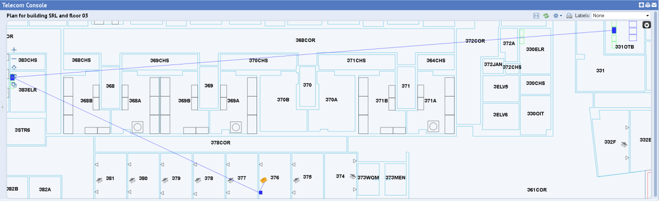
Once your connections are recorded, you can view them on the floor plan using the Trace Connections command. For example, the below image shows the connection from the workstation computer, to the faceplate in room 376, to the patch panel in room 383ELR (the telecom closet), to the patch panel in room 331OTB (the equipment room).
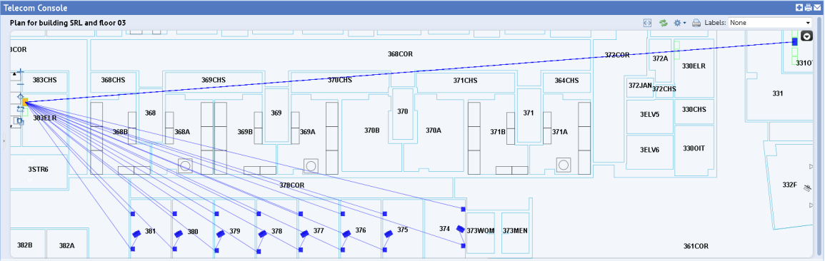
The trace can show both items toward the workstation and toward the equipment room. For example, the following image shows tracing all the ports on the patch panel in room 383ELR. The trace shows the connection to the devices in the equipment room (331OTB), as well as the connections to all the faceplates at the workstations.
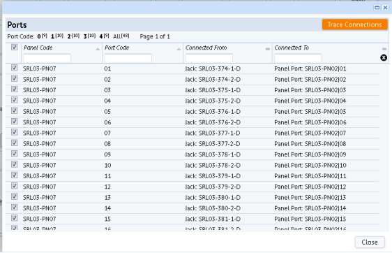
The trace feature visually shows you the connections; it does not show the exact ports on equipment or patch panels or jacks on faceplates to which an item is connected. To see this level of information, you must list the telecom connections.
You can also view connected devices with these methods:
| Copyright © 1984-2016, ARCHIBUS, Inc. Todos los derechos reservados. |