
Note: Archibus views can use one of two drawing controls: Flash or HTML. This topic covers the Flash drawing control, which can be used in custom Archibus views and was previously used in all Web Central views. Beginning with Archibus V23.2, Web Central views were standardized to use the HTML drawing control, which offers many of the same features but with some changes. See Working with HTML Drawings.
If you have a custom view that uses the Flash drawing control, follow the procedures in this topic to work with the drawing.
If it is convenient to locate an item graphically, views can present an embedded drawing with their data. For instance, if you are using a Locate Employees task, you can use the drawing tool to call up a site plan and highlight the location of the employee on a floor plan. Or, if viewing rooms organized by their standard, you can access a floor plan that highlights the rooms of a selected standard, as shown below. Highlighted drawings are handy for showing a wealth of information by location.
Web Central views, such as above, do not present the actual CAD floor plan drawing. Instead, they present an enterprise graphics file, which is a file that you publish from the CAD drawing based on publishing rules that you define.
This topic covers working with enterprise graphics in Web Central views and has the following sections:
Depending on the task at hand, you may want to adjust the display of the drawing, such as by zooming or panning.
The toolbar on the right of the drawing frame has buttons for zooming.
![]()
There are a several ways to adjust the zoom setting:
The following image shows the drawing control toolbar with the isometric view selected. The Isometric button toggles the view between an isometric and a tiled view of the drawing. An isometric view gives an elevation view of multiple floor plans. This is useful when viewing vacant spaces in a building, or when evaluating how a department's space is allocated across floors or buildings.
Views that contain drawings often use the drawing as a means of selecting items. For instance, the "Reserve a Room” view shows a list of vacant conference rooms and asks you to select the room you wish to reserve. Similarly, the Space application's Department Manager / Request Space task (shown below) presents a drawing so that the department manager can pick on a vacant room to claim it for their department.
To select a single item in a drawing, simply click on it.
The change in color of the selected area gives you immediate feedback as to which area you have selected. You can also watch the tooltip: when the cursor is directly over the internal room’s labels, a click will select the internal room.
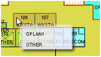
For instance, click with the tooltip as shown below to select the open plan area:
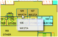
Click with the tooltip as shown below to select the workstation area:
As part of the drawing control toolbar on the right side of the drawing, some views include the Multiple Room Selection tool so that you can select multiple rooms in the drawing at one time. For example, if you want to assign several rooms to the same department, you can use the Multiple Room Selection tool to draw a rectangle around the rooms that you want to select for assignment to the same department.
There are two methods to select multiple rooms. With both methods, you draw a selection rectangle. The system selects any room that the rectangle intersects with; thus, rooms that are partially included in the rectangle will be selected. If you select a room in error and want to remove it from the selection set, click on it.
Note: The above methods work only on views in which multiple selection has been enabled. If selecting multiple rooms is not appropriate to the view, the drawing control will not include the Multiple Room Selection icon.
Often, the view displays data related to the drawing in a child frame. Selecting an item in a drawing works like selecting an element in a list: the child frames refresh to reflect this selection. For example, in the below image, the user has selected room HQ-18-115 by clicking on it. The system refreshes the child frame (Assignments) to show the selected room.
Many views minimally present an item's identifying number, such as a room number.
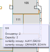
You can also hover over the room to see its information. The information that hovering displays depends upon the view and the value set in the Labels option, discussed below. For example, the below image depicts hovering over room 111 to see its employee assignments.
Some views include a Labels option so that you can display current drawing properties as text on the drawing. You choose the type of information to display (division, department, room category, etc.) by choosing it from the drop-down list. To hide all label text, including room number, choose None.
Typically, you need to zoom into the drawing in order to see the label information displayed for each room. For example, in the Create Request view, above, the user has set Labels to Category-Type. However, the drawing is not zoomed in enough to show these labels. To see an image of a floor plan drawing that does display its labels, see the Worspace Transaction Console image in the next section. If your drawing is not zoomed enough to display the labels, you can always hover over an item to see its values.
While some views automatically highlight the drawing by a various property (such as the Highlight Rooms by Standard view at the top of this topic), other views enable you to choose the information by which to highlight the drawing . Such views include a Highlights option and also present a legend so that you know the value that each highlight color represents. The Highlights option lists the various properties by which you may want to highlight your drawing; for example, you could highlight an item by department ownership, standard, category, and so on. Simply choose the property from the Highlight option's drop-down list; as you change highlight options, the legend updates accordingly.
Sometimes you may need to see multiple properties at one time on a drawing. In these cases, the view may offer a secondary highlight, known as a border highlight, which highlights the drawing according to a secondary property.
For example, the below image shows a floor plan highlighted by department and occupancy. Each room is solid-filled with a color associated with the department, and a second color (the border highlight) outlines the boundary of each room. For example, room 103 is filled with yellow to indicate that it belongs to the Electronic Sys-Engineering department and its boundary is outlined in green to indicate that the room is currently vacant. Legends on the right explain the various highlight and border highlight colors.

The highlight options, combined with the label option, can provide a wealth of information when viewing a floor plan drawing. By setting the highlight and label options, and optimally panning and zooming your drawings, you can see several pieces of information at one time.
Note: Highlight colors are associated with their corresponding record. For example, the Departments table includes a Highlight Pattern ACAD field with which you can set the highlight color to use for solid fills or border highlights of rooms according to department. The above image shows room 103, belonging to Electronic Sys-Engineering department, as highlighted in yellow; accordingly, the record in the Departments table that defines the Electronic Sys-Engineering department has yellow as the value for its Highlight Pattern ACAD field. Other highlights, such as pending space requests or vacancy highlights, are defined as part of the view. To change these highlight colors, a system administrator must edit the view file.
Views that include highlighted drawings often include a Doc button to generate a DOCX file for the drawing you have selected. You can open the document file to print the drawing.
These views often also include a Paginated Report button that enables you to create a formatted report of all highlighted drawings (not just the drawing being viewed.) When you open this document file, you can print the drawings.
After the drawing is exported, you can choose to save the file to your computer, or to open it without saving it.
If your drawings include highlights, legend colors are drawn on the background of the Web Central web page as it is rendered. This means that in order for highlights to print correctly in Flash or DWG drawing views, you must first set the following Internet Explorer option:
When using Firefox, the equivalent switch is:
You may want to control properties of the Flash Drawing Control that process a drawing displayed as part of a task. To do so, right-click while in the drawing and access a menu with these options:
In addition to the above right-click menu commands, some views offer special commands on the right-click menu. For example, while working in some views, you can place your cursor over a room, right-click, and access a menu with options for sharing the room, editing attributes of the room, or editing a move request pertaining to this room.
Choose an item from the right-click menu, and the system will present forms for accomplishing this task.
See Adding Redlines to Drawings (Flash)
| Copyright © 1984-2020, Archibus, Inc. All rights reserved. |