Archibus SaaS / Assets / IT Asset Manager / Telecom Console
Assets / Assets / IT Asset Manager / Telecom Console
Assets / Enterprise Assets / IT Asset Manager / Telecom Console
Assets / Telecom Assets / Telecom Management / Telecom Console
Connect Telecom Assets from the Grid
From the Telecom Console's left pane, you can connect equipment, faceplates, jacks, patch panels, and ports to other assets in your network. Use the Connect icon, pictured below, to access forms for connecting telecom devices.
![]()
Note: To connect telecom assets by working with the floor plan, see Connect Telecom Assets Using the Floor Plan.
Once you access the Connect form, you can model the connections of all the items that are physically connected by working with this form's arrow buttons to move to the next item in the chain.
Using the Connect Form
For the selected asset, use the Connect form to:
- specify the asset to which this item should be connected
- review the current connections.
The form lists the selected device on the left. If the item is not yet connected, the right area lists options for connecting to other devices. If the device is already connected, the right area of the form lists the connected device.
Once items are connected, you can use the navigation arrows at the top of the screen to review your connections or connect to another device, either going toward the server or going toward the workstation.
| Arrow | Direction |
|---|---|
|
|
Toward the client (workstation) |
|
|
Toward the server. |
You can use the navigation arrows to move through a series of connected devices, either toward the server or toward the workstation. In addition to viewing existing connections through the List feature, you can use the Connect form's "Currently Connected To" field to page through the connections. Note that for connected items, the form lists the connection in both "Currently Connected To" on the left, and in the fields on the right.
For example, connect an equipment item to a faceplate, click the arrow, and the faceplate moves to the left of the form so that you can now connect the faceplate to the next item. After connecting the faceplate to the jack, the user clicked the right arrow. The jack and faceplate moved to the left side of the form and the user then connected the jack to a patch panel.
As you use the form to make connections, note that it filters some of the available choices according to the items that you are connection. For example, the form lists only open ports and jacks so that you do not connect to a port or jack that is already connected.
Example: Connect Telecom Assets from Workstation to Server
Follow this general procedure to model telecom connections. This example follows the connection from workstation to telecom closet, but you can make connections to the level of detail that you require. The example shows creating a new connection from scratch, when no elements are already connected.
- In the left pane of the Telecom Console, move to the tab holding the telecom asset you want to start with.
- Click the Connect button for this item.
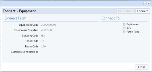
- The system presents the Connect form, which lists the item and offers choices for connecting it. In this example, you are starting from scratch, so the form lists no existing connections. If the item that you selected was connected to another device, the system would show this.
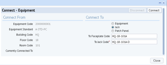
- Choose the type of item to which you want to connect the item, and then select the item from the "To" fields. In the below image, the user is connecting a workstation PC to a jack at the workstation. First, the user selected a faceplate within the room; then, they specified the data jack on the faceplate.
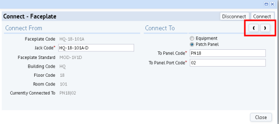
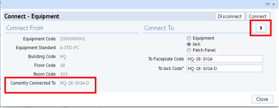
- Click the Connect button, and the system updates the connection fields in the database to document that these two items are now connected. The form lists that the equipment item is now connected to the jack, which is located on a faceplate. The system also displays an arrow in the right corner so that you can connect to the next item in the telecom path. For example, the below image shows the arrow so that you can connect the jack to a patch panel.
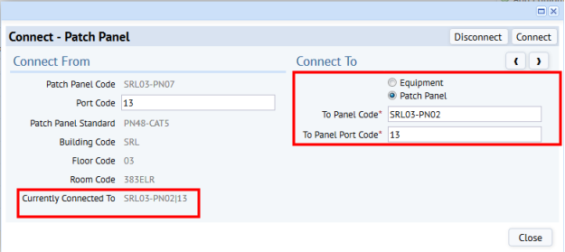
- Use the arrow to move to the next level of the hierarchy. Notice that the system lists in the left pane the faceplate and jack, and in the right pane lists the items you can connect the faceplate to: equipment or patch panels. Select a patch panel. Click Connect to connect the jack to the patch panel, and the system presents a form with two arrows so that you can review connections toward the workstation or make connections toward the server.
- You can now connect the port on a patch panel to a port of the server. Note that for this connection, the system limits you to choosing equipment whose Telecom Area field's value is Telecom Area; you cannot select workstation area equipment to connect to a patch panel.
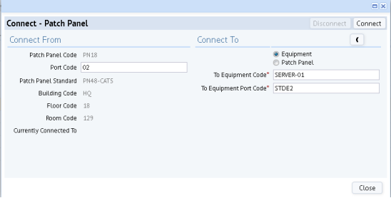
- Note the form offers an option for connecting the patch panel to another patch panel. Often in a telecom closet there is one patch panel that accepts all the horizontal cables. This patch panel then connects to a second patch panel that connects to the switch. This provides flexibility in that the first level of connection to the first patch panel can change as needed.
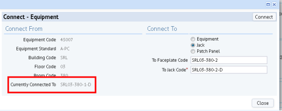
Break a Connection and Connect to a New Item
You may need to break a connection and connect to a new item. In this case, you follow the above procedure except that the Connect form will inform you that the item is already connected. In the below image, the user has entered a new jack to which to connect the equipment item. When the user clicks Connect, the system will update the database's connection fields to document that the equipment item is connected to SRL03-380-2-D and will remove the connection to SRL03-380-1-D.