Use the Telecom Console's Action drop-down list to view telecom connections in the console's floor plan.
Note: The Action drop-down list is not available when you select more than one asset type above the floor plan.
When you highlight connections, you can visualize data stored in your telecom inventory.
To highlight connections in your floor plan:
The floor plan highlights the equipment selected in step 3, and assets of the second type connected to the selected equipment.
Note: To perform another action, click Reset Highlight and uncheck all asset types before you proceed. Otherwise, the next action will not work.
Execute these steps to highlight connections between a personal computer in the work area and two patch panels, one in a telecom closet, and a second in a larger data center. To follow this example, use the console's filter to open the floor plan for building SRL, floor 03.
When you open a floor plan, Equipment is checked by default.
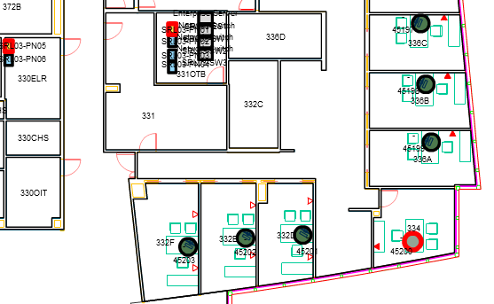
Room 334 is the corner office in the lower right of the main floor. The drawing highlights the computer with blue and yellow circles.
The floor plan highlights patch panel SRL03-PN05 in room 330ELR, and patch panel SRL03-PN01 in room 331OTB. The floor plan below highlights the computer and both patch panels in red.
Use Highlight Spaces in the floor plan to locate connected equipment in your telecom inventory.
To highlight spaces in your floor plan:
The floor plan highlights the equipment selected in step 3, and spaces that hold connected equipment in both the work area and the telecom area.
Note: To perform another action, click Reset Highlight and uncheck all asset types before you proceed. Otherwise the next action will not work.
Execute these steps to highlight spaces for a personal computer and two connected patch panels, one in a telecom closet, and a second in a larger data center. To follow this example, use the console's filter to open the floor plan for building SRL, floor 03.
When you open a floor plan, Equipment is checked by default.
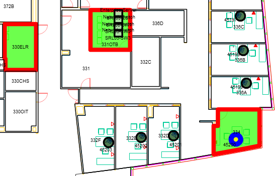
The drawing highlights the computer with blue and yellow circles. It also highlights these three spaces:
The floor plan below highlights the personal computer, and all three spaces.
Use "Trace Connections" in the Action drop-down list to open a trace report for selected equipment.
To open a trace report from a floor plan:
A Trace report for the desired equipment opens.
Note: To perform another action, click Reset Highlight and uncheck all asset types before you proceed. Otherwise the next action will not work.
Execute these steps to open a Trace report for a personal computer in the Work Area. To follow this example, use the console's filter to open the floor plan for building SRL, floor 03.
When you open a floor plan, Equipment is checked by default.
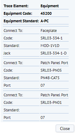
Room 334 is the corner office in the lower right of the main floor. The drawing highlights the computer with a blue circle, and opens a trace report for the selected equipment. The report shows that the computer is connected to a faceplate, and to two patch panels.
See also
Select and View Assets in the Floor Plan
| Copyright © 1984-2015, ARCHIBUS, Inc. All rights reserved. |