This topic discusses opening a floor plan drawing and working with its menus. It has the following sections:
For the other actions you can perform on the floor plan, see:
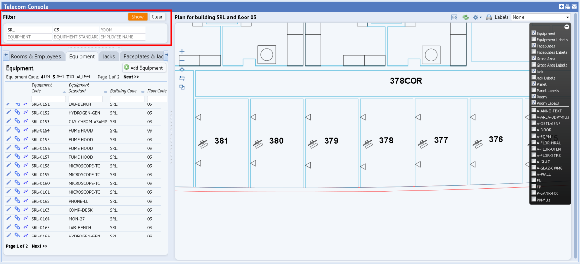
To display a floor plan, enter a building and floor in the filter at the top of the left-hand pane. Note that floor plans must be saved as enterprise graphics in SVG format in order for the Telecom Console to display them.
Once you display a floor plan, it stays active as you toggle between the Telecom Console's various tabs.
For more information on how completing the filter affects the floor plan, see Using the Telecom Console's Filter.
The following buttons are available on the left side of the drawing pane to zoom the floor plan drawing:
| Button | Function |
|---|---|

|
Zoom in |

|
Zoom Out |

|
Zoom extents |

|
Zoom into selected window area |
The Console offers these buttons for working with the floor plan:
| Button | Function |
|---|---|

|
Toggle between maximizing the floor plan and hiding the grids, or displaying both the floor plan and the grids. |

|
Reset the drawing to not show highlighted assets, highlighted rooms, connections, rooms with available jacks, and so forth. |

|
Presents a menu with options for finding available jacks:
|

|
Starts a print job of the drawing with its current settings, highlights, and traces. |
| Labels | Presents a list of text that you can display on the floor plan, such as room categories or the employees occupying the rooms. |
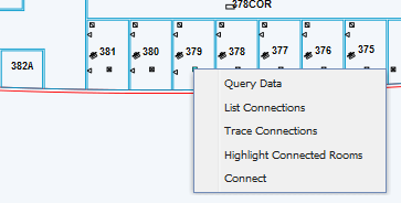
Right-click on a room or a telecom asset to access a menu that presents additional commands. For example, you can right click on a telecom asset symbol to receive a list of commands for connecting the symbol. Right-clicking on a room presents a menu with a different set of commands.
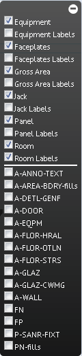
The floor plan displays with a default set of layers active. Use the toolbar in the right corner to display additional layers, such as labeling text, wall boundaries, or doors, if these items were published as part to the SVG enterprise graphics file. Click a layer's check box to toggle the layer between displaying and hiding.
Note that you may not want to display labeling text for your rooms or telecom items, such as faceplate labels, equipment labels, and path panel labels, because you can have the system identify these items by hovering over them, as described above. Turning on too many additional labels may make your drawing too crowded and hard to work with.
You can hide the label menu by clicking its expand and contract button, located in its upper right corner.
In addition to setting these drawing layers, you can use the Layers option in the upper right corner to display: Room Categories, Employees, and Room Super Categories. For example, you might want to display the employee assigned to a room or display the room category so you know if an area is a service area or vertical penetration.
| Copyright © 1984-2016, ARCHIBUS, Inc. All rights reserved. |