From the Telecom Console's left pane, you can connect equipment, faceplates, jacks, patch panels, and ports to other assets in your network. Use the Connect icon, pictured below, to access forms for connecting telecom devices.
![]()
Note: To connect telecom assets by working with the floor plan, see Connect Telecom Assets Using the Floor Plan.
Once you access the Connect form, you can model the connections of all the items that are physically connected by working with this form's arrow buttons to move to the next item in the chain.
For the selected asset, use the Connect form to:
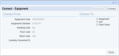
The form lists the selected device on the left. If the item is not yet connected, the right area lists options for connecting to other devices. If the device is already connected, the right area of the form lists the connected device.
Once items are connected, you can use the navigation arrows at the top of the screen to review your connections or connect to another device, either going toward the server or going toward the workstation.
| Arrow | Direction |
|---|---|
|
|
Toward the client (workstation) |
|
|
Toward the server. |
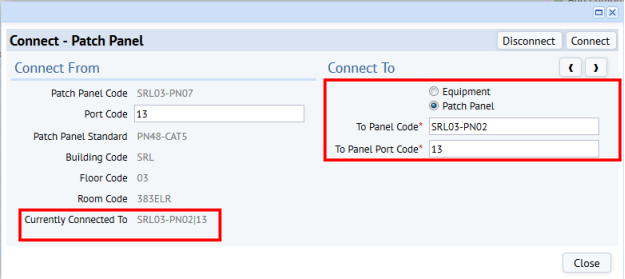
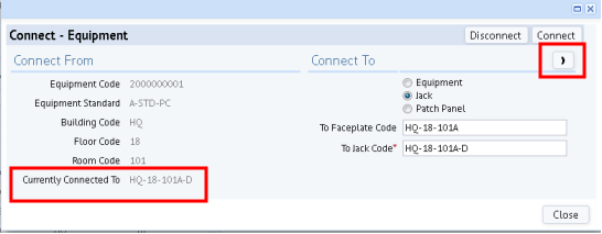
You can use the navigation arrows to move through a series of connected devices, either toward the server or toward the workstation. In addition to viewing existing connections through the List feature, you can use the Connect form's "Currently Connected To" field to page through the connections. Note that for connected items, the form lists the connection in both "Currently Connected To" on the left, and in the fields on the right.
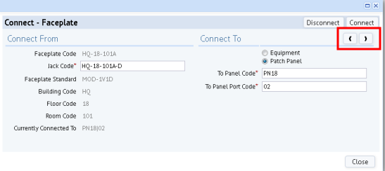
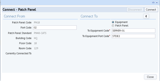
For example, connect an equipment item to a faceplate, click the arrow, and the faceplate moves to the left of the form so that you can now connect the faceplate to the next item. After connecting the faceplate to the jack, the user clicked the right arrow. The jack and faceplate moved to the left side of the form and the user then connected the jack to a patch panel.
As you use the form to make connections, note that it filters some of the available choices according to the items that you are connection. For example, the form lists only open ports and jacks so that you do not connect to a port or jack that is already connected.
Follow this general procedure to model telecom connections. This example follows the connection from workstation to telecom closet, but you can make connections to the level of detail that you require. The example shows creating a new connection from scratch, when no elements are already connected.
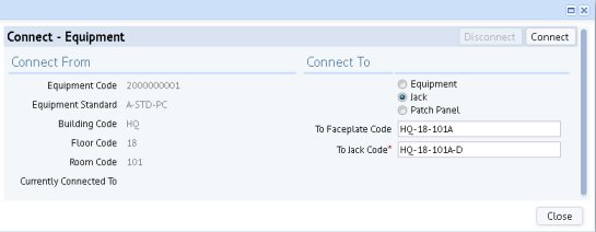
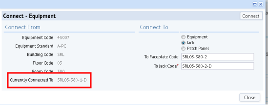
You may need to break a connection and connect to a new item. In this case, you follow the above procedure except that the Connect form will inform you that the item is already connected. In the below image, the user has entered a new jack to which to connect the equipment item. When the user clicks Connect, the system will update the database's connection fields to document that the equipment item is connected to SRL03-380-2-D and will remove the connection to SRL03-380-1-D.
| Copyright © 1984-2016, ARCHIBUS, Inc. All rights reserved. |