Archibus SaaS / Assets / IT Asset Manager / Telecom Console
Assets / Assets / IT Asset Manager / Telecom Console
Assets / Enterprise Assets / IT Asset Manager / Telecom Console
Assets / Telecom Assets / Telecom Management / Telecom Console
Connect Telecom Assets Using the Floor Plan
In addition to connecting telecom devices from the Telecom Console's grid, you can connect devices by selecting them in the floor plan. You can make connections between unconnected items, as well as make a connection by breaking an existing connection.
When connecting items using the floor plan, the items to which you connect must be represented on the floor plan. If a device exists in the database only, you can connect to it using the grid. See Connect Telecom Assets from the Grid.
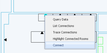
You use the Connect command, available from the right-click menu, to connect items on the floor plan.
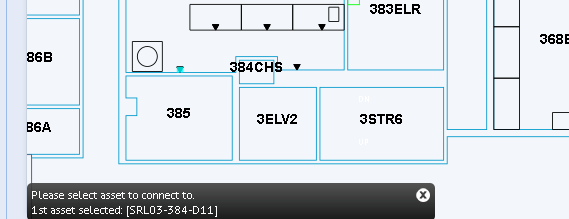
The drawing presents a message area prompting you for the items to select. For example, in the below image the user has selected the jack (highlighted in blue) and the system has presented a message prompting the user to select an item to which to connect the jack. If the item had already been connected, the message would have indicated this.
Tip: If you are connecting to jacks, you can find the jacks that are available for connections by using the Highlight Available Jacks commands, which are located on the gear icon in the upper right corner of the floor plan.
Connect to an Unconnected Item
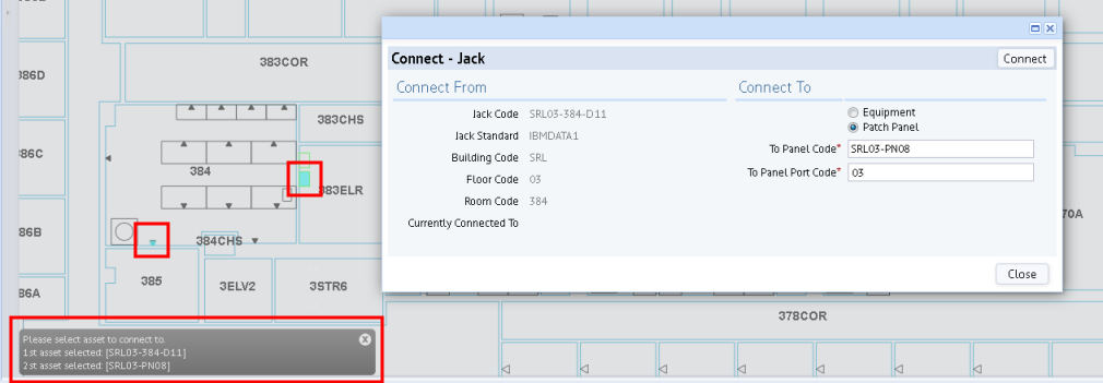
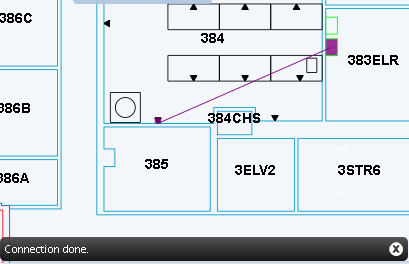
This example shows connecting two unconnected items: jack SRL03-284-D11 to port 03 on patch panel SRL03-PN08.
- In the drawing, right click on the asset that you want to connect to another asset.
- Choose Connect from the pop-up menu.
- The system presents a message prompting you to choose an asset to which to connect.
- Select an asset. In this example, the user selects the patch panel in room 383ELR (patch panel SRL03-PN08).
- The system:
- lists the selected items in the message box in the bottom left corner.
- presents the Connect form listing the jack's current connection and the item to which you will connect. In this case, the system completed "To Panel Code" with the value of the item selected in the drawing and the user entered the specific port for this panel (in this case, port 03 on patch panel SRL03-PN08). Note that this is the same Connect form used when connecting items by selecting them in the grid.
- Click the Connect button at the top of the form.
- The system updates the connection fields in the database to document that these two items are now connected.
- In the form, the system completes the "Currently Connected To" option with the selected item.
- In the drawing, the system draws a line between the connected items (the purple line in the below image).
- In the drawing's message box, the system displays a message that the items are now connected.
- Close the Connect form.
- Click the Reset button to remove the connection line and highlight from the asset symbols.
- You can continue making connections by selecting items in the drawing. For example, you might want to connect the patch panel port to a device in the equipment room.
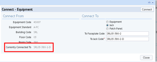
Break a Connection and Connect to a New Item
You may need to break a connection and connect to a new item. In this case, you follow the above procedure except that the Connect form will inform you that the item is already connected. In the below image, the user has entered a new jack to which to connect the equipment item. When the user clicks Connect, the system will update the database's connection fields to document that the equipment item is connected to SRL03-380-2-D and will remove the connection to SRL03-380-1-D.